
树莓派Pico的一些有趣的基本实验
Raspberry PI Pico小型MCU模块,以其价格低廉,功能丰富,开发方便为很多非电子类专业的同学进行创意项目原型设计提供了方便的平台。下面的一些实验给CDIE课程设计同学们制作的一些基本演示实验。
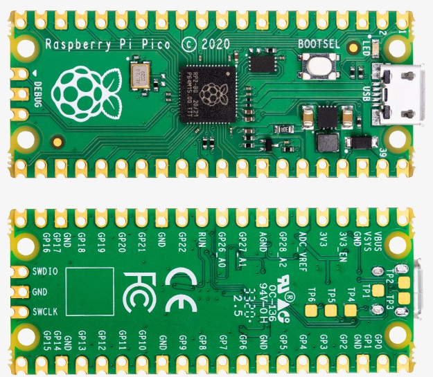
▌01 PI Pico实验板
在 RASPBERRY PI PICO 开发板 基础测试[1] 给出了对PI Pico开发板的基本设置,通过 安装Thonny开发环境[2] 可以方便对Pi Pico进行初步的开发。
本文下面根据 Raspberry Pi Pico Python SDK[3] 中给的示例,对PI Pico的一些基本模块进行测试。
关于Pi Pico的管脚配置,可以参见 Pi Pico数据手册[4] 中给出的Pi Pico管脚图定义:
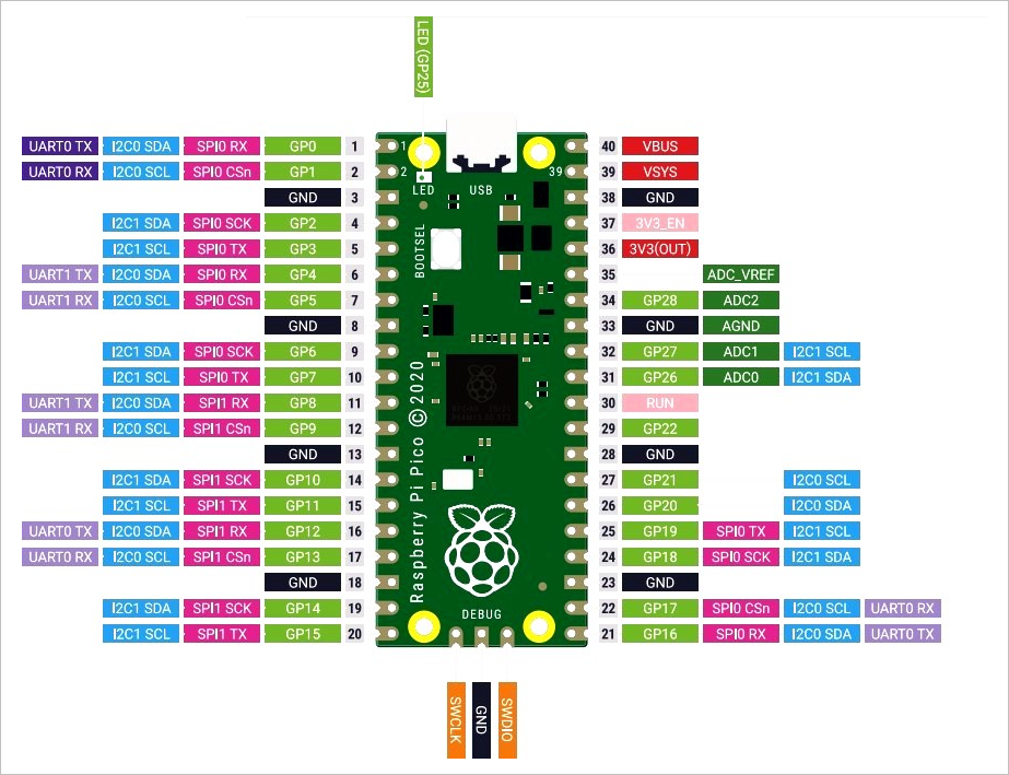
更多PiPico的资料可以从:Pi Pico官方网站[5] 获得。
▌02 基本测试
1.Flash LED on board
from machine                import Pin,Timer
from time                   import sleep_us

led = Pin(25, Pin.OUT)
tim = Timer()

print("Flash LED.")

def tick(timer):
    global led
    led.toggle()

tim.init(freq=2, mode=Timer.PERIODIC, callback=tick)
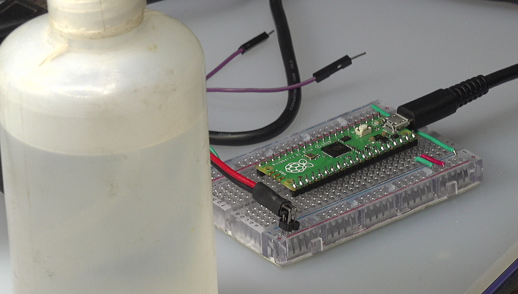
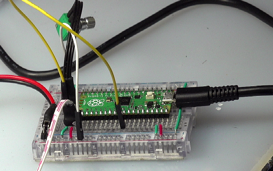
▲ 实验电路板
2.UART
(1)测试程序
from machine                import UART,Pin,Timer
from time                   import sleep_us

uart = UART(0, baudrate=115200, tx=Pin(0), rx=Pin(1), bits=8, parity=None, stop=1)
led = Pin(25, Pin.OUT)

tim = Timer()

print("Send UART.")

def tick(timer):
    global uart, led

    led.toggle()
    uart.write(b'\x55')

tim.init(freq=10, mode=Timer.PERIODIC, callback=tick)
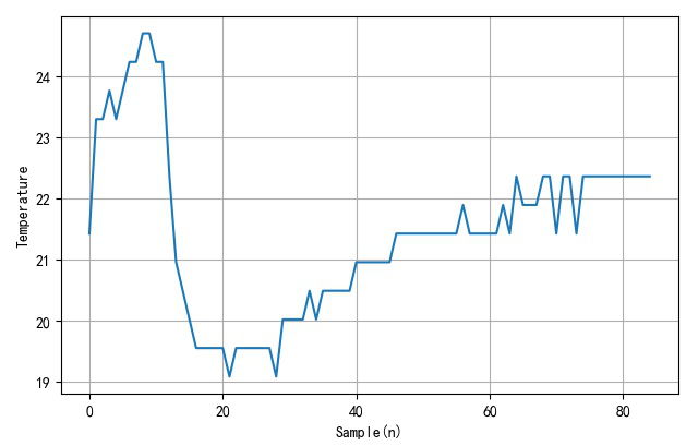
3.ADC
通过ADC通道4,读取芯片内部温度。在此过程中,使用手触摸Pi Pico表面加热,或者使用酒精喷洒芯片表面进行降温。
import machine
import utime

sensor_temp = machine.ADC(4)
conversion_factor = 3.3/(65535)

while True:
    read = sensor_temp.read_u16() * conversion_factor

    temperature = 27 - (read - 0.706) / 0.001721
    print(temperature)
    utime.sleep(2)
4.PWM
(1)PWM驱动LED
控制板载LED的波形是PWM运行。
from machine                import Pin,PWM
import time

pwm = PWM(Pin(25))

pwm.freq(1000)

duty = 0
direction = 1

for _ in range(16*255):
    duty += direction

    if duty > 255:
        duty = 255
        direction = -1
    elif duty < 0:
        duty = 0
        direction = 1

    pwm.duty_u16(duty*duty)
    time.sleep(0.001)
PWM是软件PWM,它可以设置在任意管脚上。初步测试过Pin0, 15, 16等等。都具有相类似波形。
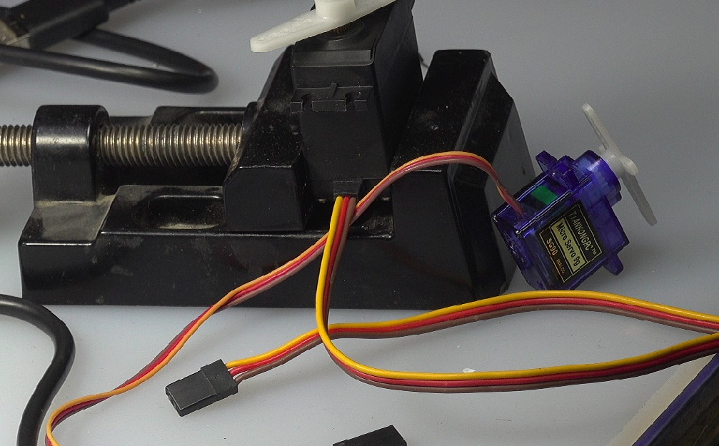
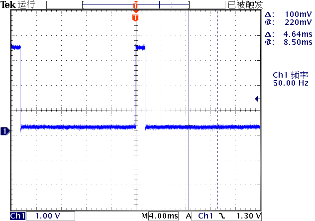
(2)PWM驱动舵机
舵机使用频率为50Hz,脉冲宽度cs 1.0 ~ 2.0ms的脉冲作为控制信号。下面是产生基本舵机位置中间时的输出控制脉冲。
from machine                import Pin,PWM
import time

pwm = PWM(Pin(15))

pwm.freq(50)
pwm.duty_u16(4915)
舵机具有三个接线:
棕色:GND 红色:+4.5 ~ +6V 黄色:指令脉冲信号
计算Duty_16公式为:
对应脉冲宽度与duty_u16之间的关系:
| 脉冲宽度(ms) | duty u16 |
|---|---|
| 1 | 3277 |
| 1.5 | 4915 |
| 2 | 6554 |
from machine                import Pin,PWM
import time

pwm = PWM(Pin(16))

pwm.freq(50)

for _ in range(100):
    pwm.duty_u16(3276)
    print("Out pulse width : 1ms")
    time.sleep(1)

    print("Out pulse with : 2ms.")
    pwm.duty_u16(6553)
    time.sleep(1)
(3)PWM+ADC实验
使用电位器将改变的电压引入ADC(0),由单片机获得对应的ADC数值,改变PWM输出,使其输出的时间宽度从1ms等比例变化到2ms。
可以看到舵机的输出角度随着电位器的改变而发生变化。
from machine                import Pin,PWM
import time

pwm = PWM(Pin(16))

pwm.freq(50)

control = machine.ADC(0)

for _ in range(1000):
    adc = control.read_u16()
    duty = int(adc * (6553-3276)/0xffff) + 3276
    pwm.duty_u16(duty)
    time.sleep(0.1)
5.中断IRQ
使用管脚PIN2的下降沿产生中断。示例程序如下:
from machine                import Pin

p2 = Pin(2, Pin.IN, Pin.PULL_UP)

p2.irq(lambda pin:print("IRQ with flag:",
        pin.irq().flags()),
        Pin.IRQ_FALLING)
使用跳线将PIN2接地。每一次等会触发中断发生一次。
▌结论
通过几个基础的Pi Pico实验,初步给出了该模块的应用实例。
参考资料
RASPBERRY PI PICO 开发板 基础测试: https://zhuoqing.blog.csdn.net/article/details/114037888
[2]安装Thonny开发环境: https://zhuoqing.blog.csdn.net/article/details/114064833
[3]Raspberry Pi Pico Python SDK: https://datasheets.raspberrypi.org/pico/raspberry-pi-pico-python-sdk.pdf
[4]Pi Pico数据手册: https://datasheets.raspberrypi.org/pico/pico-datasheet.pdf
[5]Pi Pico官方网站: https://www.raspberrypi.org/documentation/rp2040/getting-started/
温馨提示
由于微信公众号近期改变了推送规则,如果您想经常看到我们的文章,可以在每次阅读后,在页面下方点一个「赞」或「在看」,这样每次推送的文章才会第一时间出现在您的订阅列表里。